
|
|
|
|
These disadvantages were removed by the introduction of the Marconi Type 7 with a reflector 54 feet wide by 30 feet high and weighing about 20 tons, a bulk which made sector sweeping impractical. However, both transmitter and receiver cunningly used the common aerial. The transmitter itself was accommodated in a concrete room directly below the aerial, this being reached via a steel trap door.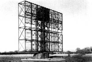 The large aerial was required for two reasons, the first of which was the choice of frequency. This was in the range of 180-220 mHz., more than double that of CH, but no higher due to the limitations of valve technology.
  The actual radiating element was a full-wave di-pole about 150 cms. long, and to create a narrow beam, eight of these were arranged in an end to end row across the steel mesh reflector. However, there were eight of these rows stacked one above the other, suitably spaced. The top 4 rows were known as the 'top array' with a middle array of two rows and a bottom array also of two rows. The intention was to exploit the idea of 'beam-switching' ( already in use in a primitive comparison form with CH ) to obtain heights, whereby alternate transmitter pulses were distributed between any chosen two of the arrays. The bottom edge of the reflector was only three feet from the ground and this was necessary as the ground aided the creation of the radiated 'lobes' of energy. Dependent on target height the two lobes would achieve differing strength of returned signal.
To obtain heights the operator simply had to rotate a switch on his console to choose which two arrays would be in use, intermediate switch points allowing all three arrays to be selected at the same time for normal use. An 'A Scan' CRT displays a single horizontal trace showing range. The separate heights display for Type 7 had two such traces each triggered by alternate transmitter pulses, and received pulses from a target were displayed only on the appropriate trace, because the return from a particular pulse was used only from the array which sent it. The two traces were arranged to be drawn on top of each other so the seemingly single line across the display showed received signals of different amplitudes from each of the two arrays for the same target and because the two signals were cunningly fractionally artificially offset, they thus appeared side by side. The ratio of these amplitudes, as judged by the operator, with the additional parameter of the range, when applied to a chart, revealed a good approximation of the target's height. To the uninitiated, the heights display showed a constantly changing and bewildering mass of upwardly pointing narrow signals popping up out of a wavering band of grass at various points along the range scale as the aerial rotated and received returns from all targets detected in say, a radius of 150 miles. However the PPI operator informed his adjacent heights operator of the range of the target in question and this enabled the heights man to concentrate his attention only on signals appearing at that distance.
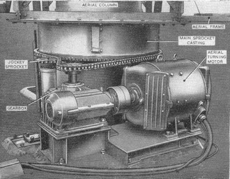 This large aerial required a 15HP DC motor (the ATM) to turn it, and this was fitted in the plinth at the base, together with a compact worm reduction gearbox and a chain final drive, the links of which were
about an inch high. At Leeming the aerial always rotated in a clockwise direction. The aerial speed of rotation was from zero to 6 rpm.,(4rpm was the usual choice) being controlled in a similar manner
to that used to control winding gear in coal mines and this 'Ward Leonard' system was housed in the Plant Room of the main GCI building. A 24 HP three-phase motor drove a DC generator,the armature
output of which was connected to the armature of the remote ATM, and on the same shaft there was also a small 'exciter' DC generator. The exciter provided the field supplies for itself, the DC generator
and the ATM. The field of the DC generator was controlled with a motor driven rheostat, giving nice push-button 'up' & 'down' control of the basic speed of the ATM. When the ATM felt the additional load
of coming against the wind, it naturally drew more current and this extra load was felt by the DC generator and the 3 phase motor which tended to slow. The exciter thus also slowed, giving reduced output.
But it had an elecro-mechanical device sensing its own field current, which on sensing a reduction increased its own field current. The exciter output rose and the DC generator and ATM fields received a
boost, hence correcting the tendency to slow. A subsequent push from the wind caused the converse of this sequence to occur and in this way steady rotation was maintained.
This large aerial required a 15HP DC motor (the ATM) to turn it, and this was fitted in the plinth at the base, together with a compact worm reduction gearbox and a chain final drive, the links of which were
about an inch high. At Leeming the aerial always rotated in a clockwise direction. The aerial speed of rotation was from zero to 6 rpm.,(4rpm was the usual choice) being controlled in a similar manner
to that used to control winding gear in coal mines and this 'Ward Leonard' system was housed in the Plant Room of the main GCI building. A 24 HP three-phase motor drove a DC generator,the armature
output of which was connected to the armature of the remote ATM, and on the same shaft there was also a small 'exciter' DC generator. The exciter provided the field supplies for itself, the DC generator
and the ATM. The field of the DC generator was controlled with a motor driven rheostat, giving nice push-button 'up' & 'down' control of the basic speed of the ATM. When the ATM felt the additional load
of coming against the wind, it naturally drew more current and this extra load was felt by the DC generator and the 3 phase motor which tended to slow. The exciter thus also slowed, giving reduced output.
But it had an elecro-mechanical device sensing its own field current, which on sensing a reduction increased its own field current. The exciter output rose and the DC generator and ATM fields received a
boost, hence correcting the tendency to slow. A subsequent push from the wind caused the converse of this sequence to occur and in this way steady rotation was maintained.
An aerial system common to both transmitter and receiver was only possible by the invention of the automatic transmit / receive switch, and in addition, a rotating transmission line coupling from the fixed equipment to the rotating aerial also had to be invented. Also the development of the now familiar Plan Position Indicator (PPI) display console was required to provide a rotating display. This huge step forward was achieved by making the trace rotate radially by the now crude sounding method of arranging CRT line scan-coils to mechanically rotate around the neck of the tube, in synchronism with the rotation of the aerial, and 'Selsyns'were used to do this. Basically these were three-phase motors, one of which was out at the aerial where it was geared to the rotating aerial mechanism and acted not as a motor, but as a three-phase generator.That was wired to a second Selsyn within the Console which rotated the scan coils around the neck of the CRT.
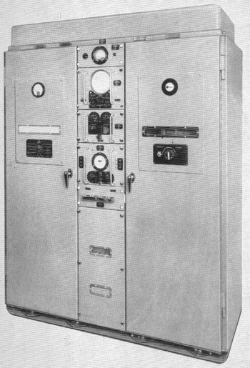
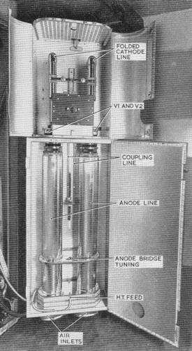
The Marconi built entire transmitter and receiver were accommodated in a single six foot tall cabinet. Duplicate cabinets were provided to ensure reliability of service and switching to the standby unit was merely a matter of powering down the defective unit and powering up the spare. At the heart of each transmitter was a pair of extremely high power cross coupled grounded grid triodes which sat side by side on a metal shelf. The associated tuned circuits consisted of six inch diameter Lecher tubes three quarters of a metre long, vertically mounted below the cathodes and smaller ones above the anodes of each valve. An additional tubing arrangement known as the 'trombone' provided the cross coupling and also transmission lines from this led eventually to the aerial dipoles. All this beautifully engineered metalwork was rhodium plated and brightly polished. The whole assembly was fixed to the inside of the righthand door of the cabinet. This oscillator burst into life every time it received the 11.5 KV 3.6 microsecond pulse from the modulator i.e. 250 times a second.
Transmission lines, which consisted of parallel thin copper tubing spaced about three inches apart, led overhead from each of the two transmitters and converged at the. . . . .
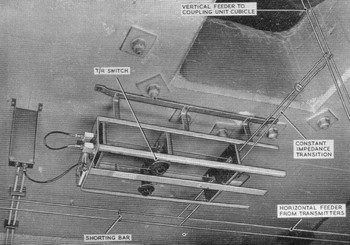 . . . . Transmit / Receive switch
mounted on the ceiling. An open framework housed
this seemingly simple device which employed a highly scientific law of Radio Frequency physics, whereby a short circuit reflects an open circuit a quarter of a wavelength away. The short circuits occured
at spark-gaps (of one hundredth of an inch) every time the transmitter pulse arrived (250 times in each second). The spark gaps were connected to the transmission lines leading ultimately to the aerial
arrays by quarter-wave stubs, one of which was also connected by a co-axial cable to the receivers. In the relatively extremely long gap between transmitter pulses, the TR switch allowed the received
signals to be routed to the co-ax, but on transmission the gaps sparked across and the five hundred kilowatts of energy now seeking this route saw it instead as an open circuit, and thus took the easy
alternative low impedance way to the aerial.
The pair of transmission lines were routed up inside the central fixed column around which the aerial frame rotated and terminated in the form of annular discs on the end of the column in a small cabin at the top of the aerial.
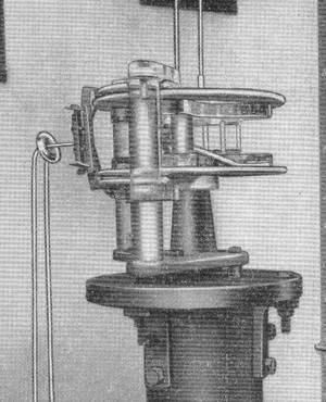 Plates mounted on the moving cabin close to the fixed annular ones acted as small capacitors through which the RF energy could flow, and although it looks crude, this rotating transmission line joint worked very efficiently. From there the pulses were fed on to a larger rotating apparatus known as the 'Capacity Switch' which allowed the energy to be routed to the various array sections of the aerial: the routing being chosen by a switch at the distant radar operator's console. The Capacity Switch was a three-phase motor driven affair and entirely unrelated to the speed of aerial rotation. Besides distributing the RF output it also determined the PRF rate. To do that the motor drove a Master Sine Wave Alternator and a Quarter PRF Alternator on the same shaft. The Master Sine Wave which could be varied in frequency between 180 and 360 cycles per second drove the Trigger Unit which fired the modulator. The Quarter PRF levels were to do with array selection. There was a large 'distributor' type three branched rotating arm on the motor shaft. At the the end of each arm was a metal plate. Four associated fixed plates were connected to a sort of cats cradle of transmission line, from which led feeds to the three dipole arrays, and the input to this was the main feed from the rotating coupling. As it arose the capacity between the rotating and each fixed plate was regarded as a short circuit by the energy and this effect electronically switched various routes through the cats cradle. It was a clever and cunning system still not fully understood by the author but clearly reminds us of the understanding of advanced RF electronics and the inventiveness of the TRE ( Radar Research Establishment ) scientists in 1941.
The valved RF oscillator in the transmitter described above would burst into life if only 50 volts were applied to it's anodes. The Modulator was contained behind the left hand door of the cabinet. It's job was to provide not 50 volts but 11.5 kV to the oscillator valves in the form of equally separated 3.6 microsecond pulses at a rate of 250 ( normally ) every second. To do this an 8kV DC supply was first doubled by means of diodes and a "ringing" choke and then applied to the input of a five section 3.6 microsecond delay line.
The Master Sine Wave fired Trigger Unit Type 2 which provided 180v 6 microsecond pulses to trigger the 'small' thyratron (thermionic gas-filled triode). That triggered the large thyratron which discharged (at 150 amps) the delay line through a pulse transformer and that fed the RF oscillators via a 2.5 kV spark gap.
The transmitter had a complex system of being powered up. This involved many relays and several thermal delay units. When either the local or remote (in the Radar Office) start button was pressed, a series of power supplies were switched on in turn and the establishment of one allowed the start of another, sometimes with a predetermined delay between. Time had to be allowed for the heaters of the transmitting valves to warm sufficiently before the EHT could be slowly wound up by a motor driven variac and applied to the modulator, and a check was made to ensure that the blower was sending its 400 cu.ft.min up through the lower lecher tubes to cool the large valves. Only after about five minutes was the Type 7 allowed to transmit. This Control Unit had only six small indicator lamps showing it's progress and could have been a source of many tricky problems, for which event we were supposedly thoroughly prepared at Locking. However in my experience it always worked perfectly - thank goodness!
Pictures very kindly supplied by Bob Jenner
Return to previous RAF Leeming page...or...Return to previous Locking page
Text © 2006 D.C.Adams
Rev280119