As may be easily imagined there were difficulties in arranging such a large reflector to turn steadily even at a slow 4 rpm through gale force winds. Two fifty horsepower DC motors were provided as standard, but four were fitted to the machines built in notoriously windy locations. As the reflector cut through any significant wind, peak currents of up to a hundred amps per phase for the motors were common, but these might reduce to thirty amps during an easier part of the rotation. Such wildly varying demand on the public electricity mains supply was most certainly not desirable, so this was allieviated by provision of a 'buffer' in the form of a motor/alternator set equipped with a very heavy flywheel reputed to be six feet in diameter. Some people claimed to be able to hear this flywheel 'sighing' due to the stress of imparting it's energy at moments of peak loads, but I never could because at those times the noise of the screaming gale drowned out everything else.
An elaborate servo mechanism precisely controlled the speed of rotation of the aerial by automatically providing a boost to the motors at moments of need and then reducing it as necessary to maintain a constant rate of rotation. 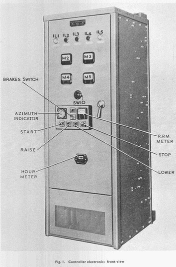 The Emotrol cabinet contained a steel encased ignitron ( a triggerable mercury arc rectifier ) for each of the three input phases and the combined rectified output of these fed the two DC motors, these being connected in parallel. The ignitron worked in similar fashion to the modern domestic light dimmer i.e. the voltage output to the turning motor armatures could be controlled by choosing the point on successive slopes of the input AC sine wave at which to fire the device, i.e. it fired fifty times per second, but the electronic servo mechanism varied the instant of the firing in such a way as to maintain a steady speed of rotation regardless of wind pressure. Hence as the reflector turned through a strong wind these currents would vary, typically 20 to 80 amps per phase, but perhaps peaking to 100. Meters on the cabinet allowed the currents to be monitored.
The actual speed of rotation to be maintained could be altered by push buttons on the cabinet and a meter indicated that speed.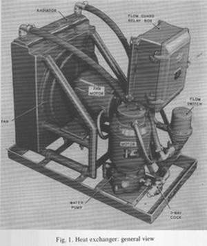
Because they were handling such heavy currents the the ignitrons had to be water cooled. Here a very low tech device was employed and is shown on the left.
A glass tube containing a metal cone was the basis of a flow gauge for this cooling system and this was mounted very visibly on the wall near the workshop. The pumped flow lifted the cone against a graduated scale.
The turning motors were mounted radially on the upper gantry. One is shown in threequarter view and is the object pointing towards the near corner of the gantry railing.
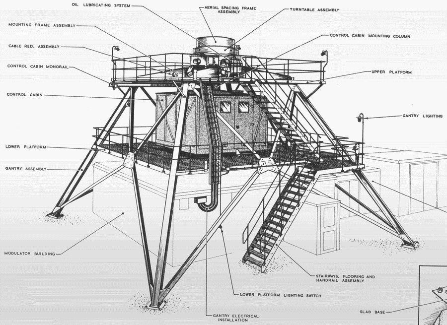
Turning motors position.
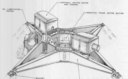
And this is the massive turntable. The ball bearings are three inches in diameter.
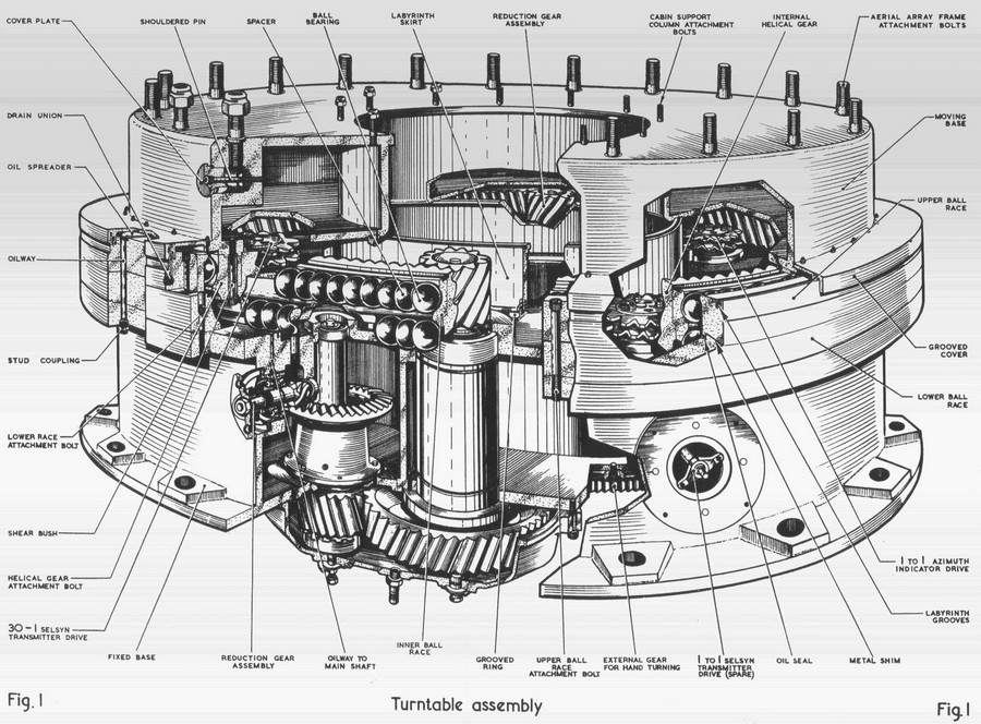
Now can you imagine having to split this massive assembly to gain access to the balls for maintenance purposes? Well it had to be done at RAF Buchan and we have a few pictures available of that hair-raising event.
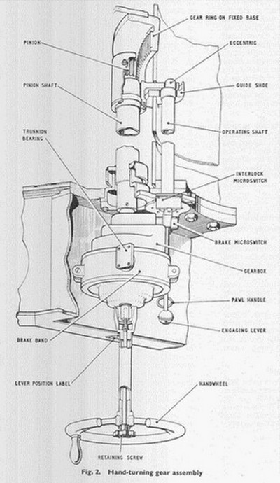
This last diagram shows the hand-turning device. I never saw it in use and I cannot imagine it being used for other than small movements for engineering purposes. It was mounted in the roof of the rotating cabin.
Pictures & diagrams sourced from the Neatishead museum and kindly supplied by Bob Jenner
Top of page...or...Previous Page
Take leave