

|
|
|
|
The CH radar at Ventnor continued in service after the war but in 1947 went to a 'Care & Maintenance' standby level. In 1950 it was refurbished and continued in use, but also in that year entirely new radar sites were being planned under the 'ROTOR' code name. ROTOR was a scheme to detect airborne attack from high flying bombers in the Cold War scenario. This involved the use of the very new state-of-the-art high powered Decca Type 80 centimetric search radar and the latest versions of the Type 13 heightfinder. The Operations section was to be completely new and to have very high protection by being installed in an underground bunker with walls and floor constructed of ten foot thick reinforced concrete, while the roof was of twelve feet thickness. (The Site Engineer in charge of construction has supplied details of its construction specially for this website.)This was expected to withstand any conventional Russian bombing. The entire construction was built forty feet below ground and with good reason it was colloquially known as 'The Hole'.
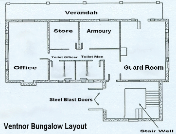 The small grey bungalow built just inside the chain-link perimeter fence somewhat optimistically disguised the entrance to the bunker. Besides providing access to the top of a circular stairway guarded by a Service Policeman, the bungalow accommodated the Technical Officer together with his Warrant Officer. The roof space above the thick concrete ceiling was almost filled with a huge water tank and a store room housed a small quantity of spare units for the radar 'heads'. ( N.B.- not to be confused with naval 'heads'!).Contrary to what might have been expected, the armoury was empty. Having exchanged one's 1250 - the RAF Identity Card - for a numbered brass disc, the Service Policeman would allow one to pass through a gate to the stair. As described in 'Early Days', the tunnel, which was about eight feet square, descended at a significant angle and was brightly lit, had smartly painted rendered walls and a highly polished brown linoleum floor. Roller skates would have served well. After about 30 yards there was a wall mounted glass fronted cabinet which contained two service revolvers. It was hard to imagine their purpose, especially when the bullets for these were kept in a safe in the office above. The corridor continued, then turned sharply left and after another thirty or so yards reached a pair of massive thick steel blast doors. At no time did I ever see these doors closed. The corridor was then at the right-hand side of a large room known as the Radar Office to which a wide doorless aperture gave access.
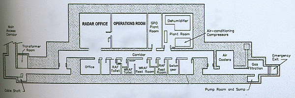
After the Radar Office entrance, doors on the right gave access to Officers' and Other Ranks' refreshment rooms and on the left double doors led to a few steps down into into a large 'plant' room. Having neither false floors or ceilings to accommodate vast amounts of cabling & large air conditioning ducting, as had the previous rooms, it seemed so much vaster. Here were ranks of grey motor driven equipment and air-conditioning apparatus. The corridor, now being only six feet across, continued through double doors and around a corner to a bolted heavy steel door through which was the main ventilation shaft which doubled as a route to the emergency exit. The shaft contained a zigzag of several flights of steel stairs and a large waterfall air washing system but that was not in use. Ascending further, a heavy door in the side of the shaft, now a steel tube, finally opened to the reassuring fresh air.
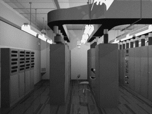
The name 'Radar Office' was somewhat a misnomer, the only desk being a small one for the shift diary, although there was a partitioned office in one corner. The majority of this thirty feet square room room was filled with rows of rack-mounted electronics. The valve technology of that time was bulky and generated vast quanities of waste heat, so each rack was fitted with forced air cooling, and thus the noise level within the room was irritatingly high, possibly because the sound was being reflected from the polished teak floor. Some of this equipment was my concern, but the vast majority was not. Each of the radar transmitters required a timing signal to initiate each modulator pulse, and these had to be in synchronism otherwise one radar in receive mode might be force fed with the pulse being transmitted from its closely adjacent neighbour, with dire result. So all timing pulses were derived from one master and that was generated from an extremely stable crystal oscillator at a high frequency and repeatedly divided down to the 270 rate required, and this equipment was deemed to be the province of the above-ground engineering staff, and was contained in but one rack amongst the serried ranks of the many others in the Radar Office.
And the contents of the many other mysterious cabinets? Well for example there were Range Rings and Video Map, which rightly belonged to the 'Consoles' trained fitters and mechanics, and although the author knows only the outline of the operation of these, a few words are appropriate. Range rings were bright concentric rings which, at the flick of a switch, could be made to appear on the display at the same time as the targets. They were at set distances apart, say 50 miles, and thus the operator had an easy way of assessing the range of a target. The pulses to create the rings were generated entirely electronically, but Video Map required a little more ingenuity. Here, also switched on as desired, an outline map of all the coastline in range, together with a grid map, was superimposed on the display as a background image, allowing the targets to be seen at the same time. The source of the map image was an acetate sheet on which all the details were accurately drawn. Over this was mounted a lens which concentrated the image onto the aperture of a photo-electric cell. Under the acetate sheet was the face of a six inch white phosphor CRT. This did not display the radar echoes but just a bright radial line which rotated in synchronism with all the proper displays. Thus the map was scanned and the PE cell produced an output which could be distributed to the consoles as a video input. The beauty of this system was that the timebase (operator selectable) at different consoles could be set to different ranges but the map always expanded or contracted in proportion, as did the range rings. The Video Map required careful setting up but was extremely effective, and there were two of these units in the Radar Office.
Another remarkable apparatus was the Monitoring system. This aid to fault-finding was a relatively large-screen oscilloscope which was built into the racks at a central point and the screen could be slewed to facilitate easy viewing. It was fitted with two large rotary multi-position (perhaps 20) switches. Combined use of these allowed hundreds of crucial waveforms from countless sources within the Radar Office to be displayed. Reference to a bulky volume of diagrams and photographs revealed whether or not the one on the screen was correctly formed.
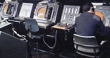
A curtained archway in the side of the Radar Office gave access to the similar sized Operations Room. Darkness ruled here, the only normal illumination coming from the amber and green glows of the CRT displays and that from what may be described as a dynamic Plotting Table. 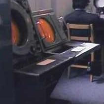 Arranged around the room there were three pairs of consoles consisting of an amber fifteen inch Plan Position Indicator (PPI) driven from the Type 80 or Type 14 search radars together with a green nodding height finding display fed with the returns from from a Type 13. In addition there were a greater number of individual Type 80 driven consoles. The origin of the trace of a PPI search display was normally the centre of the CRT, but operator controls allowed this to be moved to any point of the surface. If moved say to the south west periphery then only the north east 90 degree sector was viewable, thus concentrating the operator's interest in that area but allowing a much greater range to be monitored.
The Ventnor Type 14 was mounted on a 25 foot high wooden gantry and this arrangement gave good very low level cover to and beyond a more distant horizon. Thus shipping was effectively monitored together with low flying aircraft, the two being very easily differentiated by the size of echo and the huge difference in speed of progress. Casual chatter was banned in this room, the only voices heard were those of the operators quietly relaying information via telephone headsets to a distant central Control establishment or occasionally directly to an aircraft by means of VHF radio. Our radio equipment was located across the valley at Stenbury Down where the two necessary towers still remain today.
In the Cold-War context, contrary to what might be supposed, there was no living accommodation down this Hole. However, small rooms were provided for relaxation purposes together with a tiny kitchen.
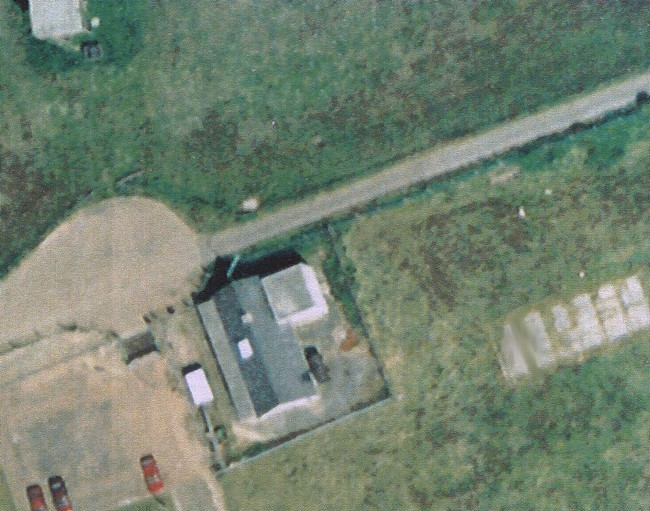
The water supply arrangements need a mention as St.Boniface is the highest point on the Island. George Sutton (ex RAF Police) has provided these details. There was a forty foot Braithwaite water tower situated close by just outside the perimeter which held no less than 36000 gallons and that was topped up by regular pumping from the Lowtherville street level under the control of a civilian contractor. In turn it supplied the very large tank situated in the roof of the bungalow. Bob Jenner has provided this excellent and unrivalled view from the air of both the bungalow and the water tower. It was taken some years after the RAF had departed.
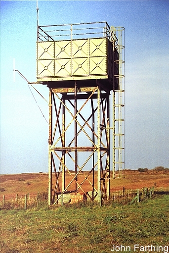
This picture of the water tower has been kindly provided for exclusive use here by John Farthing, formerly of Plessey Radar and now a local war-time historian and author.
Drainage would also have been a problem. The underground lavatories were akin to those used by submariners and the subject of many jokes and warnings of mishaps, so I somehow contrived to avoid their use. Equipment to deal with these vital services must have existed in the Plant Room, so this would have been the province of civilian contractors, known within the Service as 'Works & Bricks'.
Suitable period pictures of a 'Hole' in operation are rare. Those normally available show the present day state of such i.e. dismal concrete chambers stripped bare of all furnishings and equipment. Those would only serve to detract from the image I hope I have portrayed: one of quiet efficiency, of cheerful young uniformed people getting on with a worthwhile job in a most professional manner.
Footnotes:
1) The two plans were adapted from those found in N.J.McCamley's most excellent and revealing work entitled "Cold War Secret Nuclear Bunkers", which I heartily reccommend as an interesting read. ISBN 0 85052 945-X published in 2002 by Pen & Sword. It contains many photographs taken by Nick Catford.
2) I am indebted to John Higton who was a National Service radar mechanic at RAF Bempton in East Yorkshire in 1958, a site similar to that at Ventnor. He has been engaged in the construction of a 3D computer model of the R1 'hole' and has been able to provide the true dimensions of the installation. The entrance corridor was indeed 8 feet square, the Radar Office 31 by 27 feet, and the Operations Room 31 feet square. The emergency exit within the ventilation tower required no less than seven steel staircases to reach the surface.
John's work has been completed in the form of a most excellent DVD which provides his 3D walk-through model of the Bempton Hole and a rotating Type 80. Done to provide a permanent record of the
Bempton site, it applies equally to all R1 installations, complementing the above written description perfectly. The DVD is available for purchase from the RAF Air Defence Museum at Neatishead,
Norfolk.
Text © 2006 D.C.Adams Rev150516
Water Tower photo© 2008 John Farthing